Week 1: Principles and practices, project management
This first week my classmates and I were really excited to finally start the Fab Academy we had heard so much about and were waiting to get into. The first classes were not quite as active as I had expected, but it made sense since it was just the introductory course. I was a bit confused at first about the difference between Fab Academy as an official class and with MDEF. There were some other students in the main hall with us that were going to be joining in for Fabacademy. The first lesson about getting set up with Git and how Git works was informative as a refresher of the semantics behind it. However, I wish that I had received more of this general overview when I started coding and using GitHub. If I had not been familiar with any of the coding experience from first term, I think I would have been very lost so it did feel nice to feel like I knew what was being talked about. I’m still a little confused about how MarkDown works and how we will be using it for our new repositories with each challenge we do. I had no idea what the first global class would be like. Our MDEF group chat was inundated with messages because we did not understand exactly what the assignments were or what was expected of us, but I think it is more clear now that we will be focusing on what the local Barcelona classes are assigning for us. I’m not sure if I’ve ever been a participant in a zoom call with that many people before. It was awesome to be able to see FabLabs from all over the world and see how it really is an interconnected network of so many people of different backgrounds, each learning in their own spaces and then coming together once a week to learn collectively through zoom.
This week’s task was to look through previous students’ websites and note the way they documented for Fabacademy. By looking at other websites for documentation, I was also browsing and reading through, which helped me grasp what concepts I will be digging into and learning about which made me scared but excited. One thing I liked was from Ines Burdile's website. She broke up the weekly reflection in four different sections: facts, findings, feelings, and future. I think documenting like this was probably useful in helping Ines encompass the Fabacademy for herself and future readers as well. From Paco Flores' site, I noticed that he provided a link to all the github repositories that was highly visible. This made it easy for the viewer to view the documentation more in depth and also allow future students access to it if they needed. One thing I really liked from Morgan Shaban’s website was that she included initial and final questions. By opening up the beginning of the week like this and ending it with continued, but more developed and informed questions seems like a really good way of extending the week’s learnings. In the coming weeks I’d like to experiment with some of these ways of documenting as well as my own. I’ll start today.
Key Takeaway: Git is so important in coding technologies because of it’s open source model, collaborative functionality, and keeping a log of changes.
Question: What is the difference between Git and Linux and which one is used when?
Moment of !: Realizing what a big community of people who are doing the same thing I was being connected to globally.
Week 2: Computer-aided design
For the week 2 introduction to Fab Academy, we focused on what could be done using computer programs in design. I was familiar with the terminology in terms of 2D digital design such as vector vs. raster, color formats, file format and quality, etc. We were told by Victor about different programs to use for 3D design along with explanations in 3D modeling styles. We learned about parametric design, which I see how it could be useful in a lot of applications, but would not be sure when it would be necessary to use it or not. We then got introduced to the 3D modeling program blender, which I had never used before. I never understood how programs like these could manage to be open-source when they are actually pretty advanced and offer a lot of features for free to its users. Blender was said to be “not in the same bucket as computer-aided design, but I don’t fully understand why. While explaining, Victor seemed passionate about Blender as a program and resource in itself and said that he has spent time writing code for plugins he wanted to create. The more and more I hear about open-source programs like these, I wonder if in the future and see it as a way forward to a more inclusive space in tech. Will it create too much competition with superpower companies such as Autodesk that charge 100s of dollars for their programs one day? I feel that there is a space for both. The beautiful thing about open-source programs such as Blender is that users have a choice to contribute some monetarily, and with this the company is able to hire some full-time employees to develop the program, as well as a large community of people that is willing to support and help one-another within the software.
Key takeaway: There are many many options of programs to choose from when it comes to 3D modeling, each with its own strengths in certain applications
Question: why shouldn’t parametric design be used in all modeling?
Moment of !: Open-source programs such as Blender are able to grow and stay alive because of the collaborative community of people that use it.
Assignment: We were instructed to design and create a 3D model related to our projects and then create a poster incorporating 2D elements to display it.
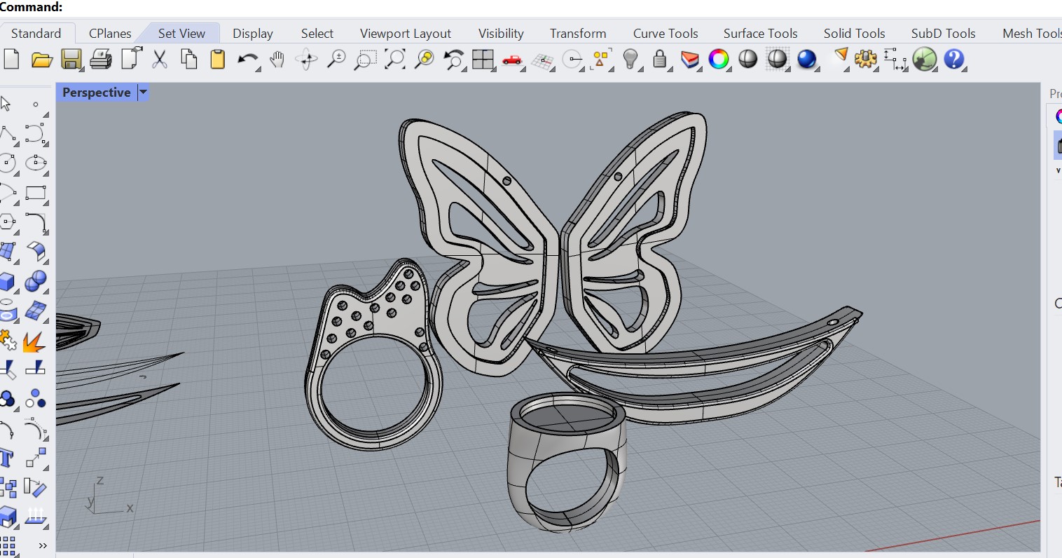
I hadn’t posted any 3D modeling that I had done previously, so have a post here for the end of year project. I needed to model some jewelry that could be printed with growlay filament, a porous 3D filament that supports the growth of seeds. With this printed jewelry, we will be able to create wearable, living jewelry for our final event Symbiatipico during the MDEFest. I modeled the pieces in rhino and then printed them at IAAC.
Week 3: computer-controlled cutting (Design and Computer aided manufacturing)
Going into this week, I was excited to hopefully get started on using the machines. Our main focus was on using the laser cutter and vinyl cutting machines. I actually enjoyed learning about the mechanics of the laser cutter, it is a fairly simple machine that can have different types of lenses and lasers such as CO2, neodymium, and fiber. We got demonstrations of both machines. I’m not sure if I had even realized there was a vinyl cutter in the FabLab. It seems like a fun machine to use for stickers and such, especially for doing things like screen printing which Santi showed us some examples of. Josep went through the process of creating a small piece with the laser cutter. Neither machine seems very complicated to use, and I have used the laser cutter before, so I think I just need some firsthand experience and practice with it to actually get it down. The main things with using these machines, along with any computer aided design, is to think about how the pieces will act in reality beforehand, such as allowing tolerance in the kerf, nesting to minimize waste, how pieces will fit seamlessly together, etc. This is why the emphasis on doing a test beforehand is so important.
Key takeaway: As long as parameters are set correctly and everything is checked/verified before using, laser and vinyl cutters are relatively easy to operate.
Question: What is the advantage of designing in 3D for a piece that is going to be cut in 2D say on the laser cutter?
Moment of !: LASER is an acronym, and it stands for light amplification by stimulated emission of radiation.
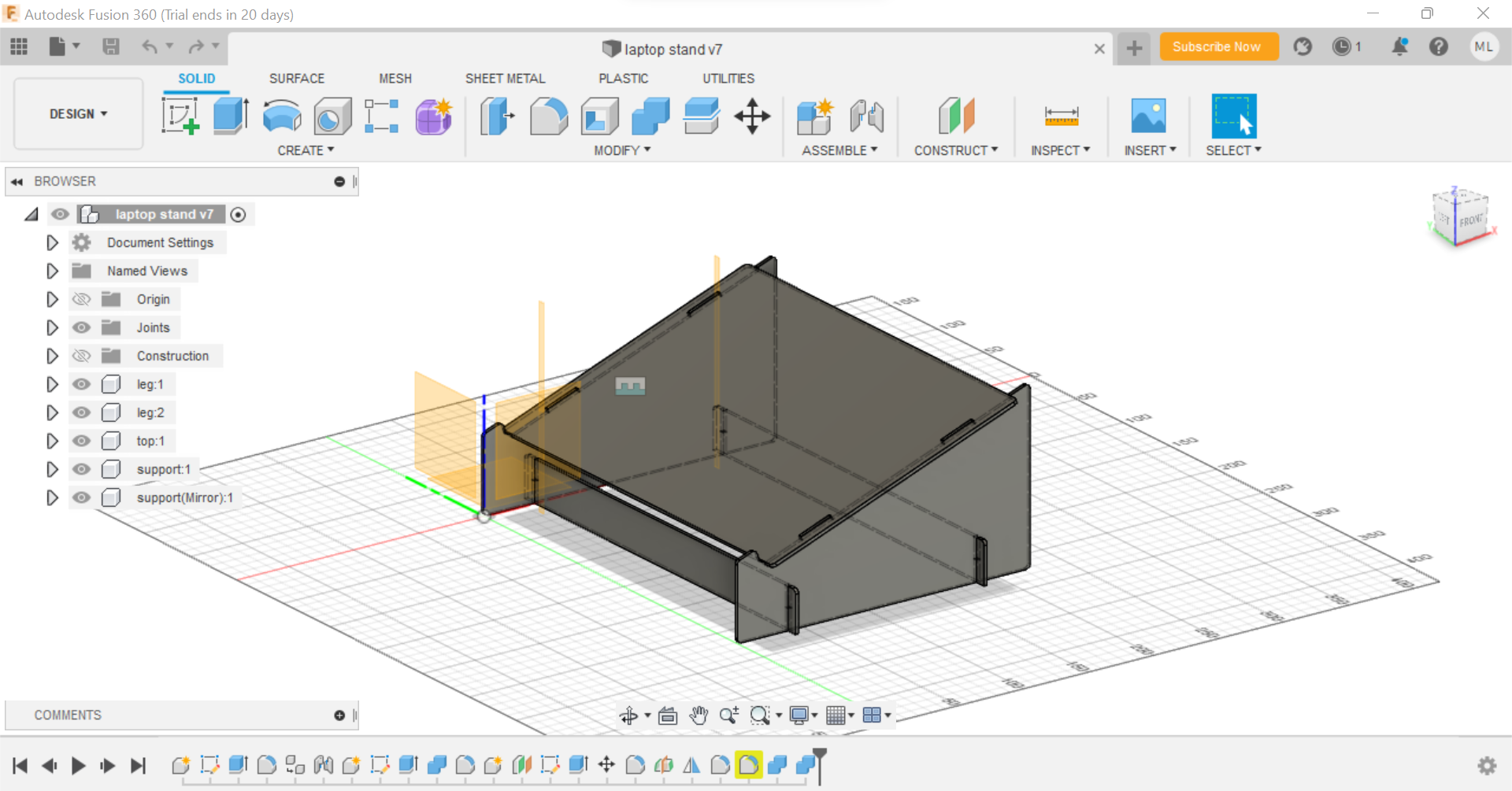
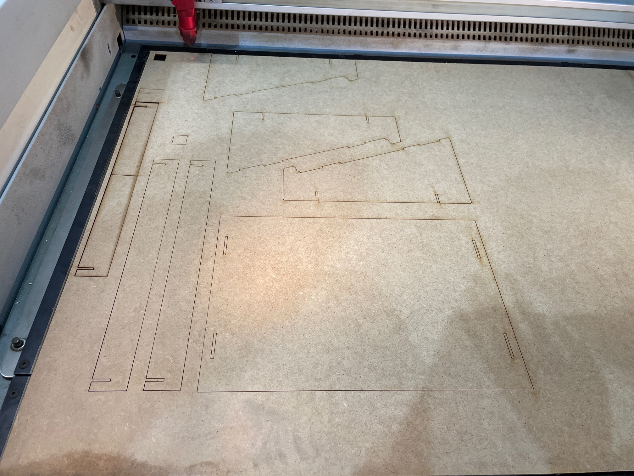
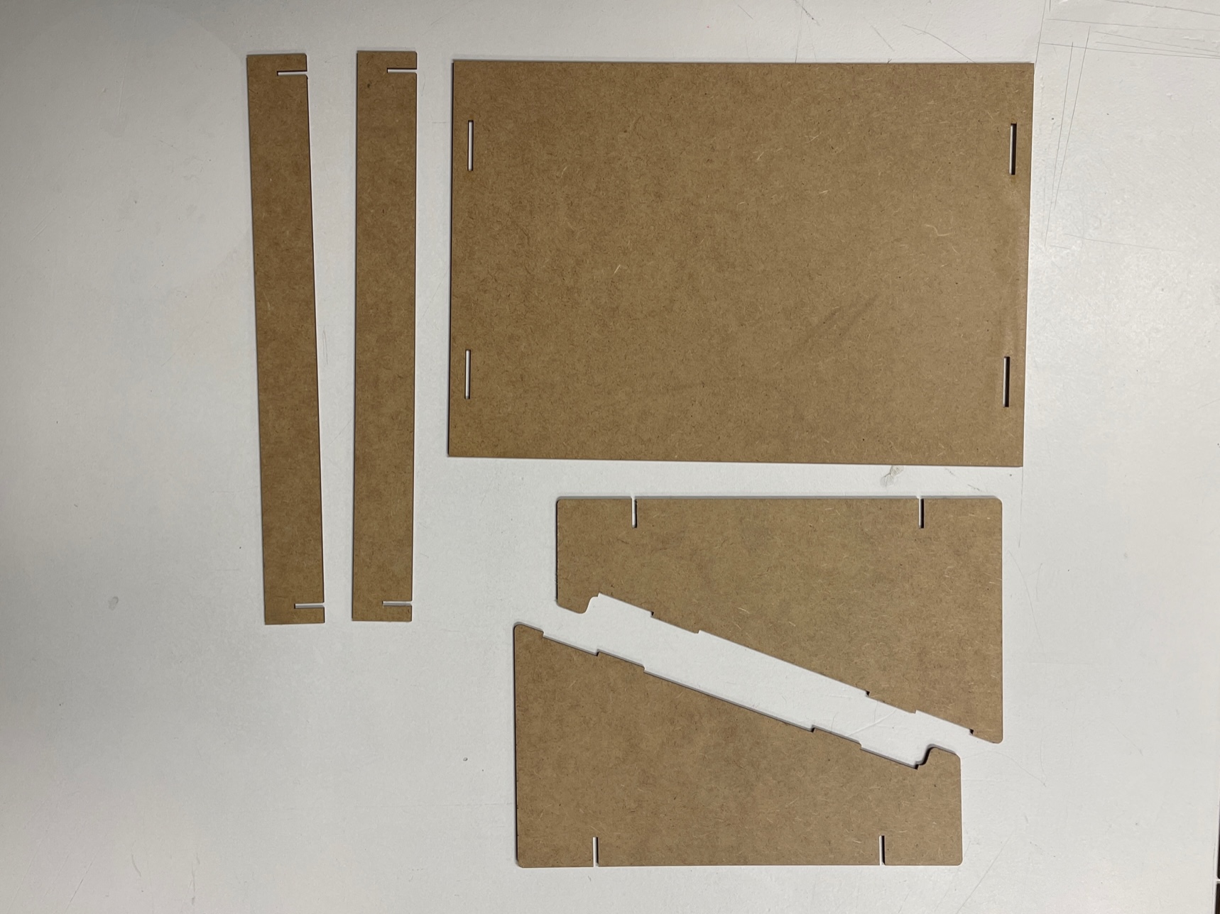
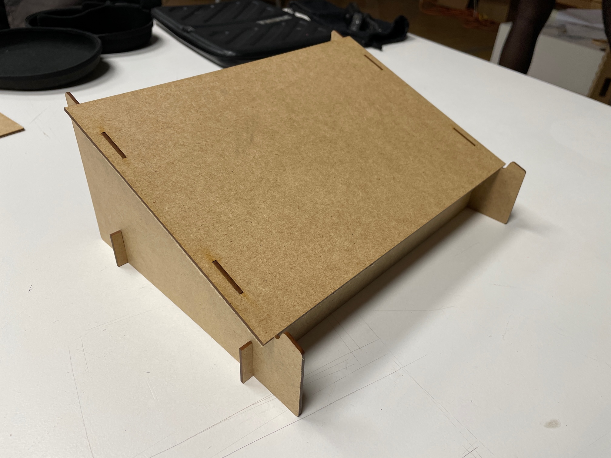
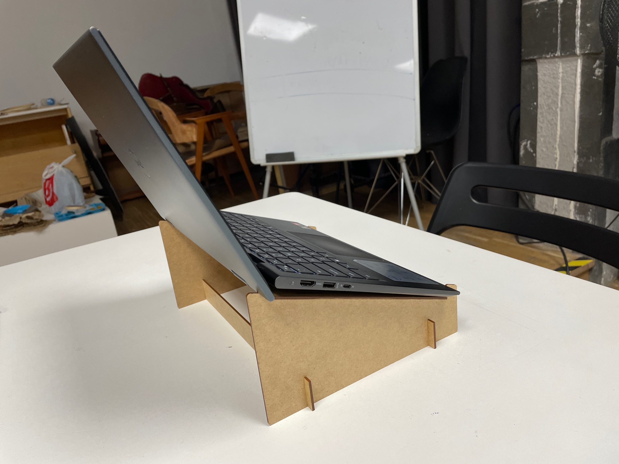
Assignment: Create a press-fit model using parametric design and produce it using wood/cardboard on the laser cutter and pass the pre-use machine test. With this assignment, I was very excited to use the laser cutter. However, I had to build the model first. I originally wanted to make some type of small decorative shelving system for my room. However, I had never used fusion before and felt I needed the help of a tutorial. Using fusion for the first time was intimidating and confusing, as I didn’t grasp onto the workflow quickly. I wanted to design something in strictly 2D that I could then cut on the laser cutter and put together afterwards, as I felt I could have created something much cooler and more fun than the laptop stand. However, I successfully designed my first parametric design in Fusion. I’m actually using the laptop stand right now! After finally sending the file to be cut, the press-fit joints fit together perfectly which I was surprised about because I was convinced that it would not have worked. After this exercise, I can say I’m confident and excited about using the laser cutter, but that I still need more work to get comfortable with fusion.
Week 4: Electronic production (Design and CAM)
We continued with the hands on-learning this week, this time shifting our focus a bit to electronics. We learned all about PCBs- printed circuit boards. It was rather enlightening because I had no idea about types there were based on substrates, the result being different thicknesses, flexibility, and options of single or double sided PCBs and multilayered ones. At Fablab Barcelona, FR1s are used. The PCBs are made using many techniques. These include etching; using chemicals to eat the copper away, milling; cutting away at material, using a fiber laser; which has high quality and speed but may create microscopic-scale defects, and vinyl cutting; to create flexible plates but can be difficult to weld. We went through the setting for the milling using modsproject.org. It was honestly really hard to follow along, there were so many settings which I felt I would not remember. Using the machine to mill the PCB was an interesting process to watch, and also included multiple steps which I feel I would need to be reminded of if I use it again. When we got to solder the PCBs, I really enjoyed the process because I’m a fan of soldering and welding. You have to be very precise and watch what you are doing in order to make sure it works well.
Key takeaway: PCBs can be made using a variety of techniques, each with its own purpose and some may be better choices than others based on the application.
Question: How are the designs for the PCB boards made?
Moment of !: flexible PCBs can be made using the vinyl cutter and can even be used with textiles.
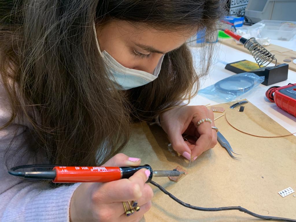
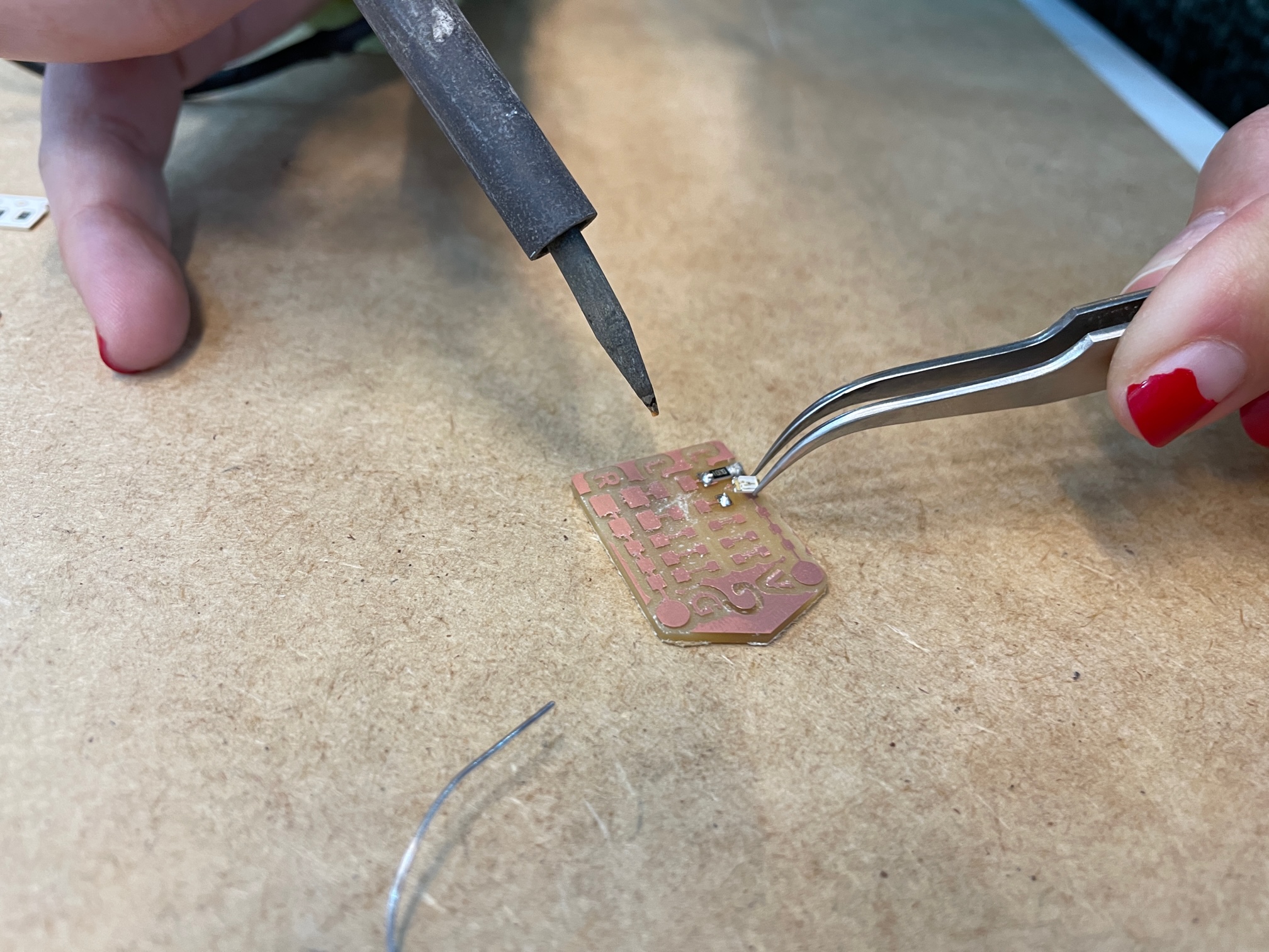
Assignment: Finish (by pairs) your LED BADGE soldering the smd components and test it(make the led light up with the power supply) Paula Del Rio and I soldered our board together in class (we forgot to take a picture of the final product). It was fun to solder the tiny pieces to the board. Using the multimeter, we got to see the light turn on which was satisfying. I would like to do more of this in the future.
Week 5: 3D printing and scanning
Again with fabrication tools this week, we got to move our designs and thinking from 2D into the 3D realm. The main advantage of additive manufacturing in the fashion of 3D printing is that it has zero or minimal waste since the material is used specifically and exactly in the place and amount it is intended to. It allows for complexity and freedom in design in a fast an easy way. However, it is better for small-scale applications and may have poor surface definition and tolerances. It was interesting to learn about technologies for 3D printing including bath and extrusion (FDM) which is the most common method. While seeing the 3D printers at work, I was able to see how useful and imperative using supports were for some shapes. We were also able to see the difference between infill and shells, and how minimal material could be used while maintaining maximum strength. We then got to play around with the Kinect 3D scanning and photography. It was impressive to see how 3D photography can work with large areas of points and images, and understanding when it is better to use 3D scanning versus photography.
Key takeaway: a huge variety of materials can be printed with.
Question: are there currently any applications where 3D printing is used/more efficient for commercial mass production?
Moment of!: Paste printers can be used to print with a variety of “wet” materials that must be the perfect consistency.
Assignment: 3D print an object you have modeled (not something you have downloaded) that could only be made with Additive manufacturing techniques.
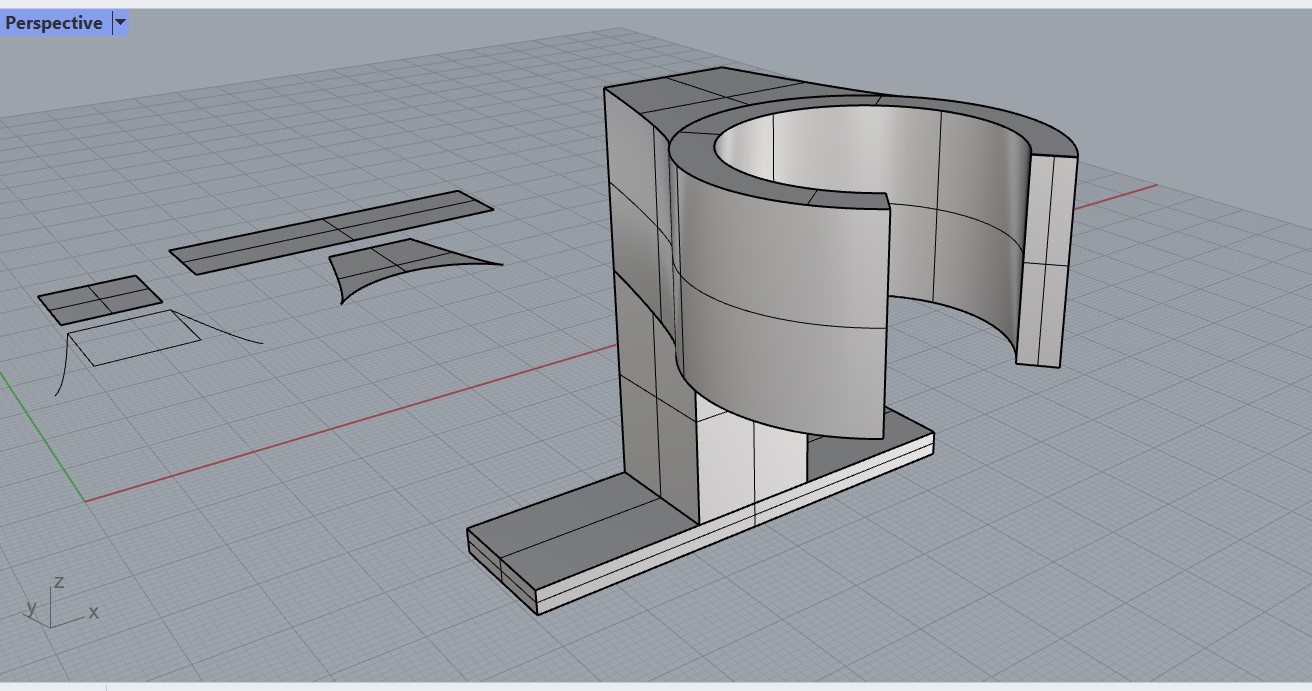
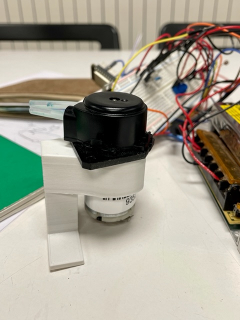
In order to get the pieces we needed to fit to specifics we wanted for the photobioreactor, we decided to model pieces to print for the pumps and sensors. We needed a 3D printed piece to hold the peristaltic pump so that it could be held in place upright, and then screwed to the base of the photobioreactor. The holder has a neck that fits snugly around the pump’s body. I measured it, modeled it in rhino and then printed it on the ender printer with white PLA filament.
Week 6: Electronics design
This week we learned about electronics design starting with reviewing components and what they do including types of resistors, capacitors, diodes, mosfet/transitors, etc. We then explored electronic design (EDA) softwares. The one we began with using was kikad which you can use to design schematics of connections then create physical layouts with footprints. Josep led us on the course with explaining how kikad works with a follow-along lecture. I, along with some of my classmates, found it a bit difficult to keep up as there as so many small steps and I was having some problems loading the specific files and libraries onto my computer. However, at its core the program does not seem too difficult so I think with some experimentation I should be able to figure it out.
Key takeaway: thinking in terms of a workflow in terms of what you want to do using eda softwares to design PCBs for electronics keeps things clean and simplified
Question: how complex of a system of connections can be created using a program like kikad?
Moment of!: it is vital to first understand the functionality of all the components in order to design a well-thought out PCB board.
Assignment: Design a PCB board also called breakout-board for your ESP32 HUZZAH 32 microcontrollers ( or other board that you want to use rapberri pi ,etc) that allows you to connect an input (sensor) or an output (actuator) to your commercial board without cables. Include the design files in your webpage and explain well the process on how you did it.
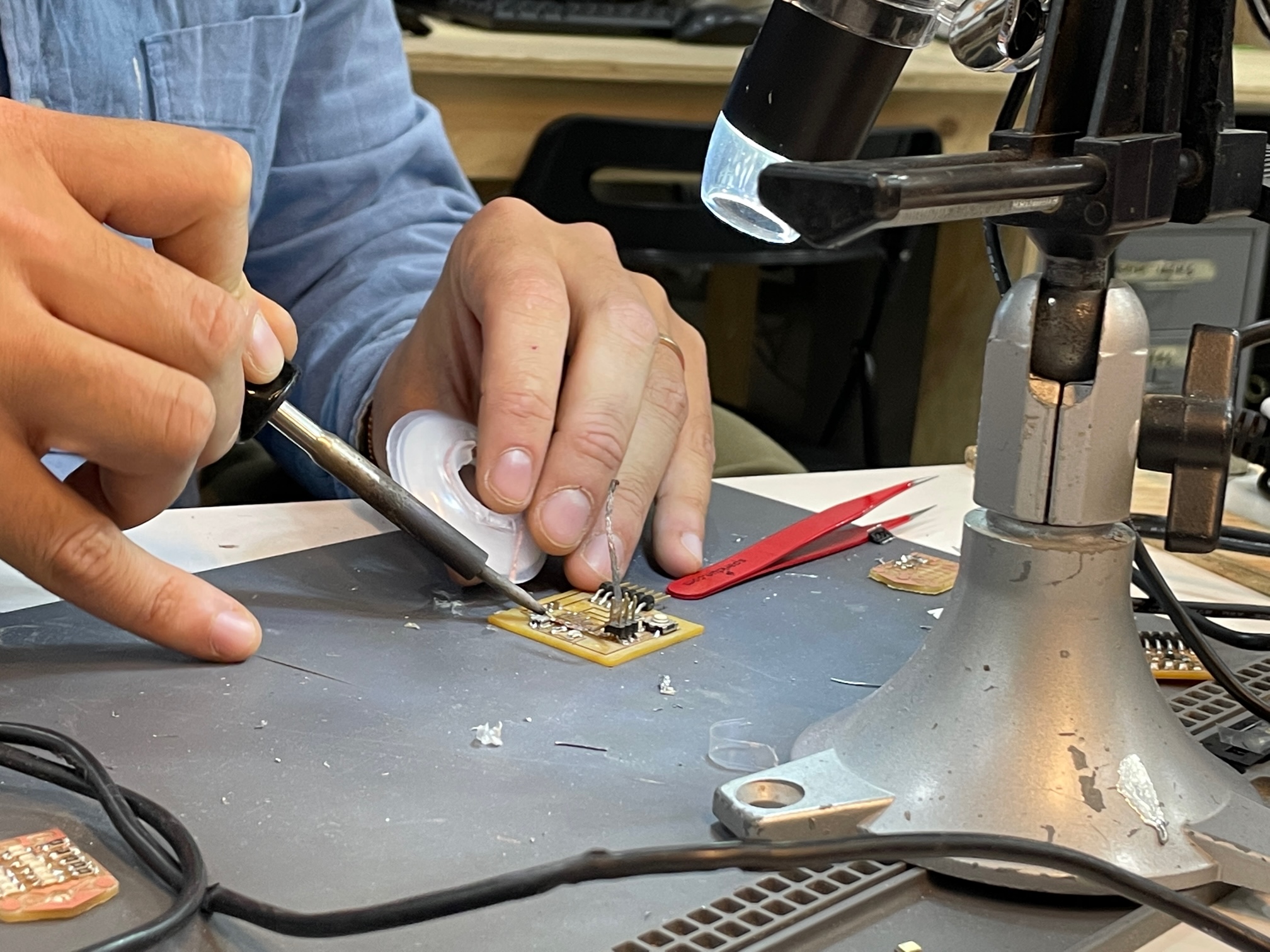
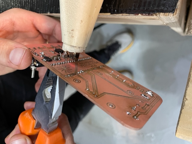
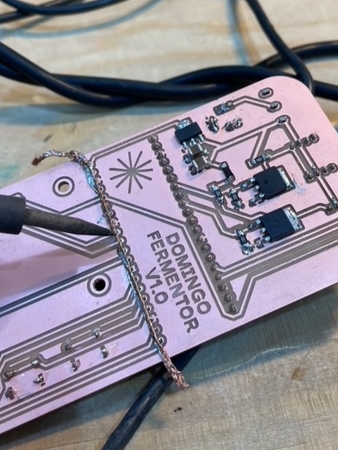
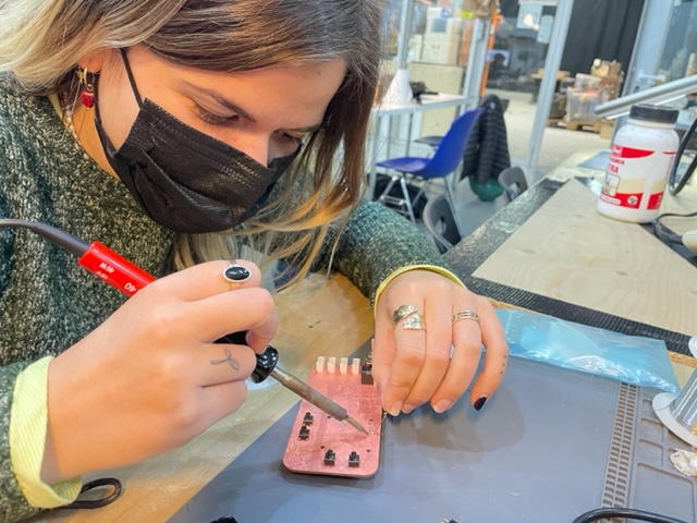
Before creating a new PCB, Pippa and I milled the PCB from the Domingo Club’s open-source incubator that we were building. It was helpful to do this as we could see how milling it worked and examining their schematics and the connections on the circuit. We milled the PCB and soldered all the pieces onto it only to realize.. That we had milled it on a double-sided PCB sheet which meant that the board was conductive everywhere, which is a problem. We learned from this mistake and re-milled it on a smaller, one sided one.
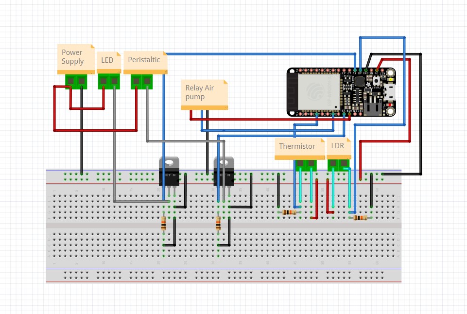
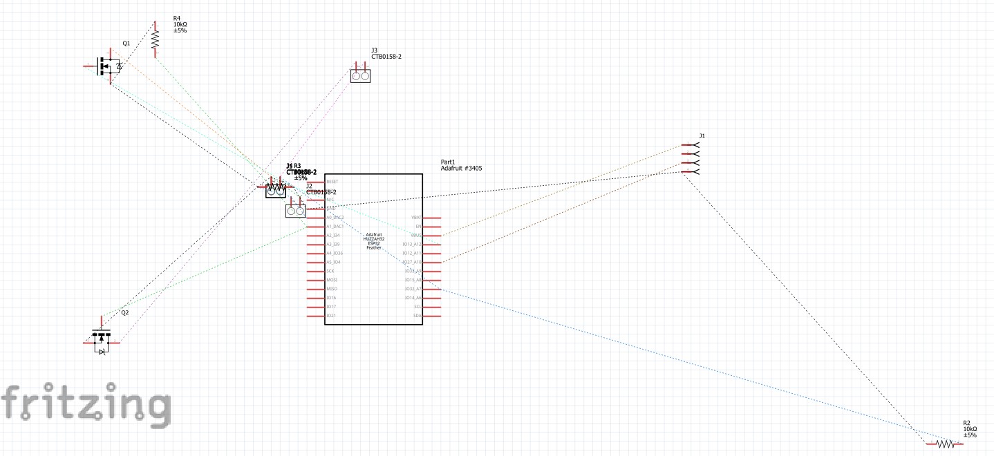
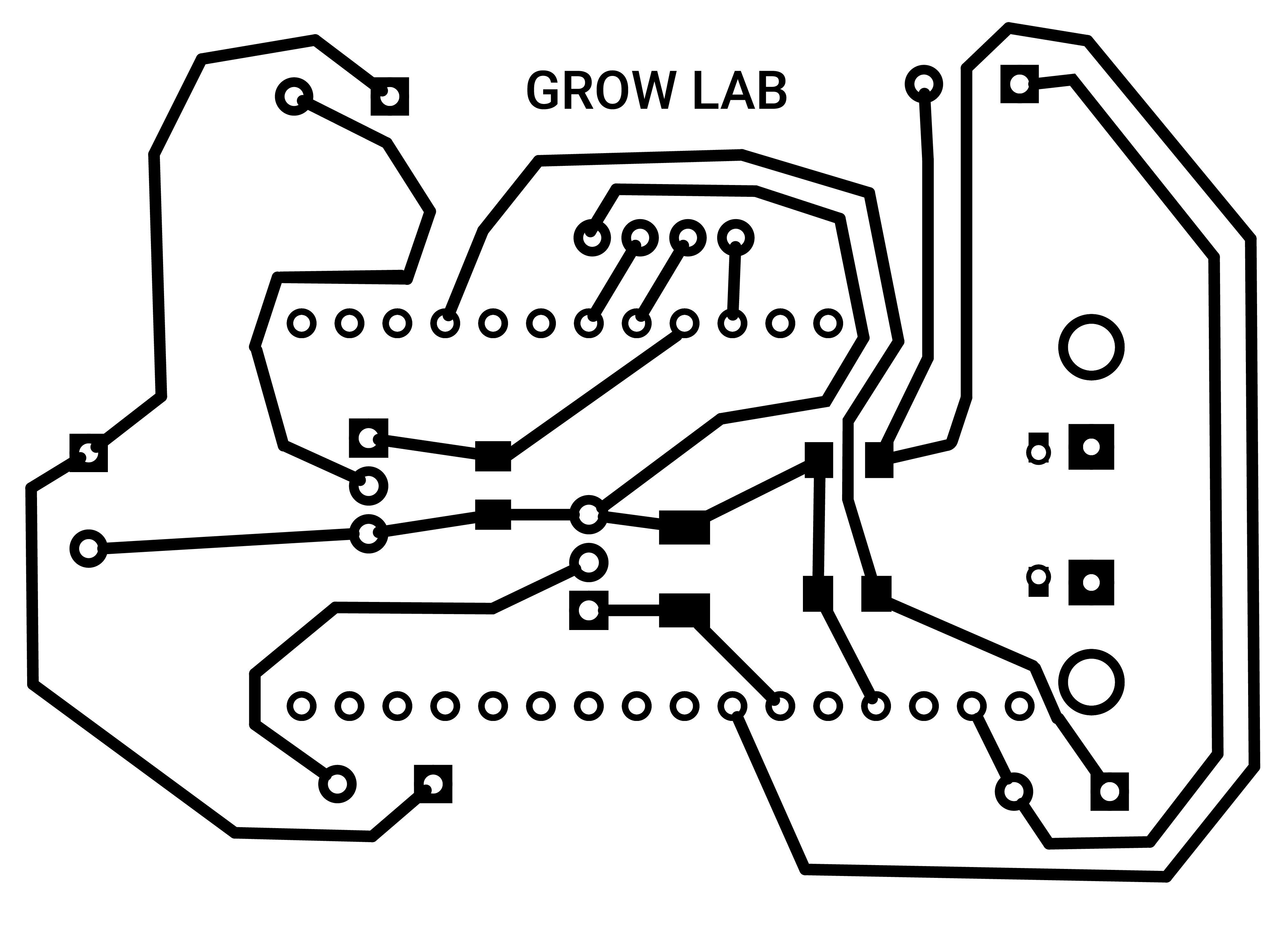
For the next PCB, we needed to create one to control the elements of pumps, lights, and sensors for the photobioreactor. We wanted to measure light intensity to see if the PBR needs more light, temperature to see if the water drops too cold, and pumps to get air flow and circulation. In order to do this, first the electronics needed to be set up and protyped using a breadboard and wiring. Next, this was moved to a schematic on fritzing where you can drag and drop elements to see the connections more clearly. Fritzing has a function where it automatically lays out the connections onto a PCB, but it needed to be cleaned up.
Week 7: CNC milling and CAM
Back to physical production this week, we finally got to use the big CNC machine! I have been looking at this big, loud machine all year so it was about time we got to use it. CNC milling is a subtractive technique, where material is cut away with a big drill. It is good with automation because it is fast, accurate, and flexible in that it reduces a number of other machines and processes. We got explained the difference between spindle (quieter, stronger, controlled by computer) and router (less expensive, for soft materials, speed controlled by hardwear) motors. We also learned the difference between automatic and manual lubbing. Some things to note were to remember to account for kerf, think about joint styles, drill bits cannot be used synonymously with end mills, and more flutes equal higher quality.
Key takeaway: CNC milling is well used to make specific parts that are often made with wood or metal.
Question: what is the thickest piece of wood an end mill can cut through?
Moment of !: CNC, which stands for computer numerical control, isn’t used exclusively for the mill, but is used in many types of machines
Assignment: Design something big IN PAIRS! . You can use up to a maximun of half full board ( that means 1200x1200mm) of the available material per student. 15 mm thick pine plywood boards.
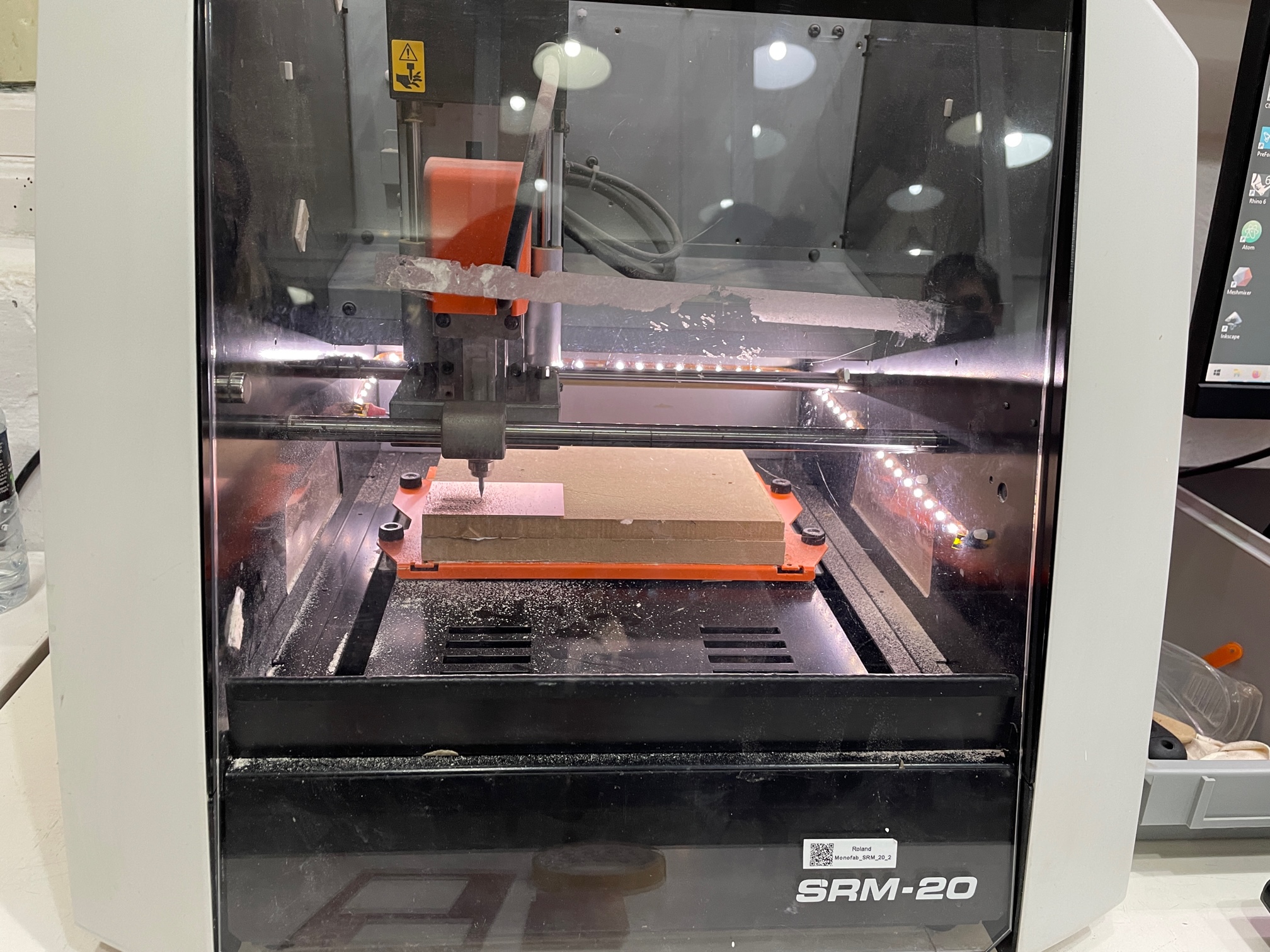
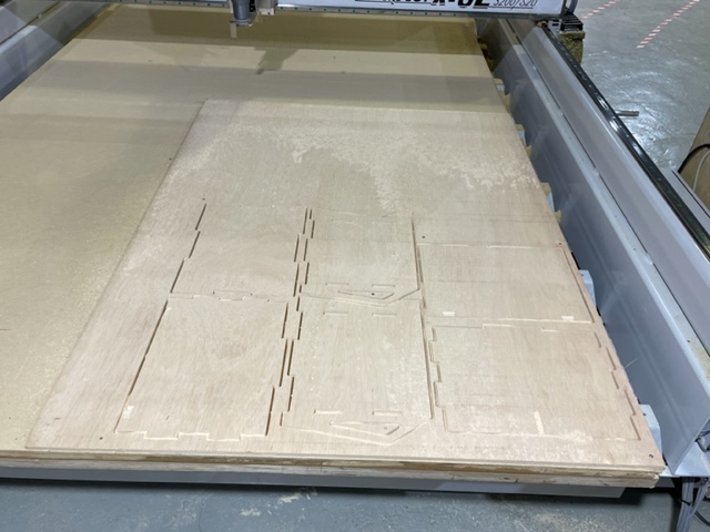
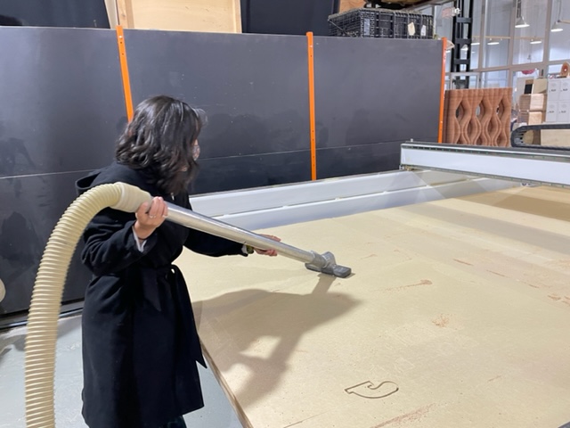
This task came at the perfect time because I was able to use the machine for the open-source incubator Pippa and I are building. After ensuring the files were formatted correctly, we decided to use RhinoCAM to send the files and get the g-code because it worked better than easel. There were many, many settings and it took a while to set up. Josep was kind to help us with this, but I know it will take me a couple more times with assistance to fully be able to do the whole process of CNC milling by myself. Once the g-code was ready with the specified thickness of wood, we secured it down in the negative spaces and started the cut. It was exciting to watch the machine as it moved deeper layer by layer to reveal the cut design. The result was the body of the incubator which fit together quite nicely, without the need for much sanding. The experience was fun using the machine, with screwing, using the vacuum, and carrying the huge piece of wood.
Week 8: Embedded programming- how to make a computer
We firstly started going through the history of computers, going through analog vs. digital and continuous vs. discrete. We then discussed transistors again, hardware and firmware versus and operative system. The human aspect was gone through, with the different levels of languages, our language being closest to object oriented and visual language. We then tried out problem-solving with flow-charts. Doing this exercise, I realized sometimes solutions seem so clearly to go one way when they can be directed some other way depending on the questions asked beforehand.
Key takeaway: It is better to spend time thinking about what you want to do to build structure before writing any code.
Question: when starting to code, what might be the best way to understand the logic of how computers read code before writing?
Moment of !: machines (computers) are dumb, and need all direction on what to do from us!
Assignment: Use your programmer (HUZZAH32, ESP32 Feather) to program a circuit with a “led and a button” to do something
Week 9: Molding and casting
I was sick this week, so I was bummed to miss the in-person class to learn about molding and casting which can be a very fun craft. I had a look at the presentation and had my classmates fill me in about the lesson and answer any questions I had. Molding & casting have been around for centuries such as with pottery. When making molds, you must think about whether it is one or two-sided, and whether or not it should be cut in two in order to remove the mold. Molds can be made using the CNC machine with wax or foam. When designing the mold, it is important to think of the shape in terms of edges, negative space, alignment, and how the casting material will flow. Casting can be done with hard or soft materials depending on the application.
Key takeaway: The main thing with molding and casting is to think about the final product in a reverse engineering way in order to see how the mold should be created.
Question: Can wax molds be melted and be reused again?
Moment of !: In addition to thinking about the molding material, the casting material properties should be well understood in order to prevent mistakes.
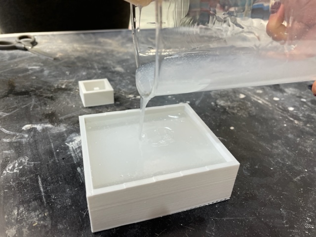
Assignment: Make a mold (can be 1 or two sides) hard-soft-hard. 3D print- cast silicone- cast something inside. You can use biomaterials to substitute the silicone or the final cast. Experiment!
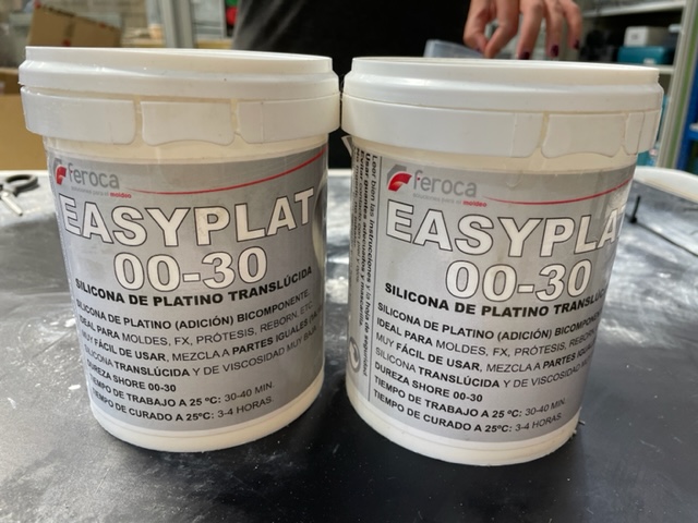
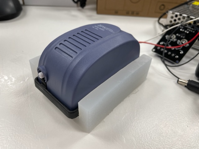
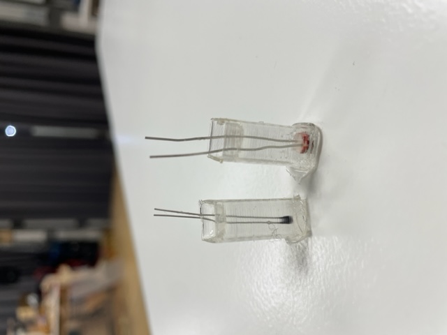
For this assignment, it made sense to make molds for components we needed for the photobioreactor. During this process of making the molds, I think the most challenging part was thinking in reverse- how the mold needed to be the inverse of the actual shape I wanted and how the negative space would look. With Paula, we created several simple molds. One was for the air pump, so that it could be encased by a soft material and not sit directly on the wood, making it quieter when it vibrates. We also modeled molds to encase the sensors. We ended up making two types of molds for the sensors, as we found out that the clear silicone would not be a strong enough material for the sensor and it broke up when we were taking it out. Therefore, we chose another mold style to use resin with. For the pump stabilizer, I poured silicone parts A and B in equal proportions, mixed, and poured into the mold. After waiting 3-4 days it was fully dried, and I peeled it away from the mold.